Hardware Information
Much of the hardware for the Turing machine is custom built, although all the motors, servos and electrical components are off the shelf items. The photos and captions detail each of the machines parts. All the images can be clicked to view an enlarged image.
Read/Write Head
The read/write head is the center of the machine. The tape in the machine is a 1000’ roll of white 35mm film leader. The characters are written by the machine with a black dry erase marker. Each character cell is 1.125” in width. Although the tape is not infinite in length, it is long enough for any practical use and can hold approximately 10K bits worth of binary data.
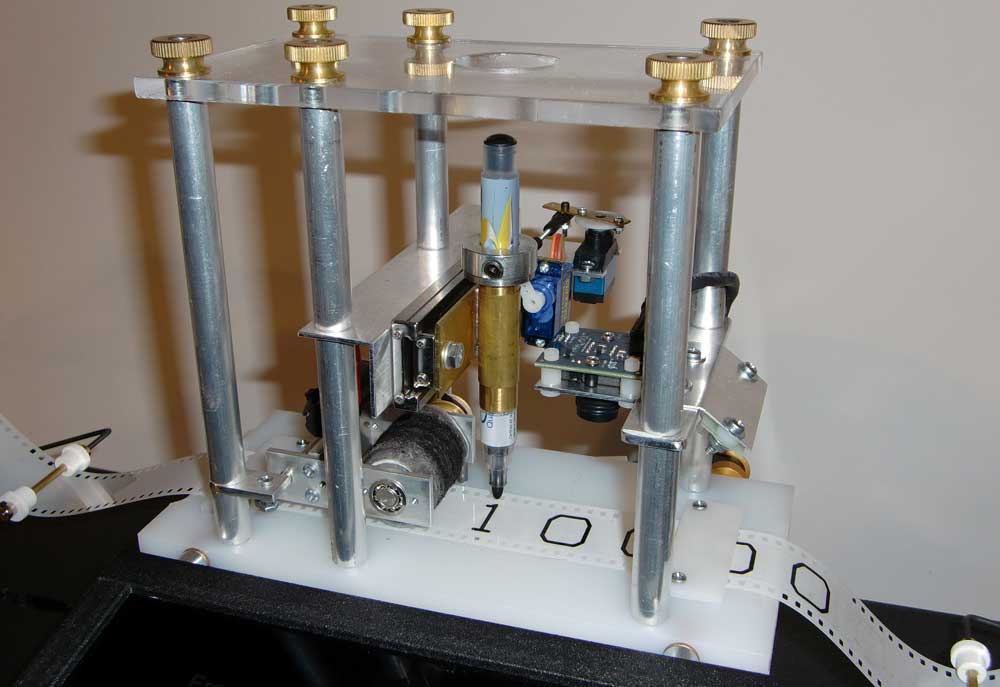
The read/write head from the front
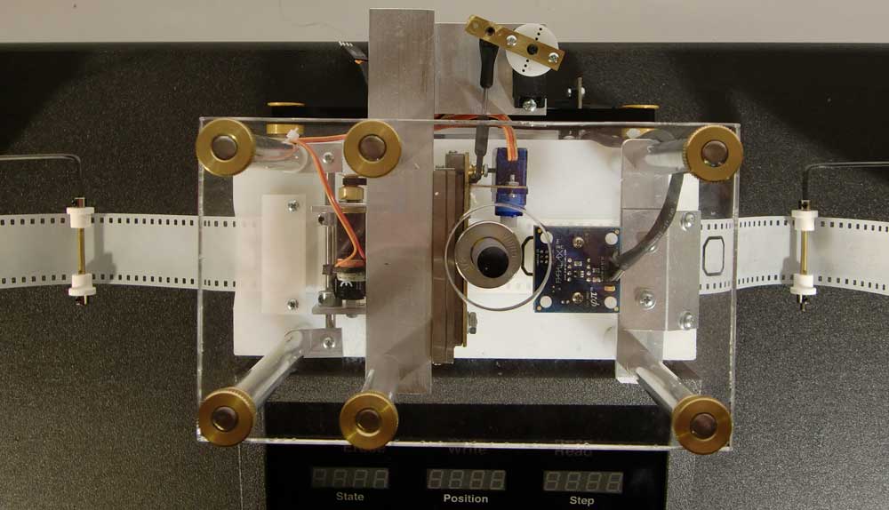
The read/write head from the top. Here you can see the servo that controls the "Y" axis of the pen. The base of the head is 8.5 x 4".
View from the back of the head showing the transport system. The stepper motor is at the lower left and includes a home sensor. The toothed pulleys are sized so that one revolution of the motor is one cell of the tape. The top belt tensioner controls the relationship between the two film drive cogs.

Here is one of the film drive cogs with its cover/hold down moved aside. There is one cover at each end on the read/write head base.
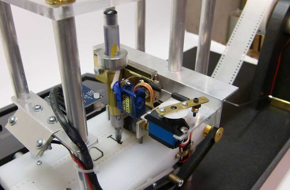
Back view of the write section of the head. Here you can see the two servos, one for the Y axis, the other for pen lift. The pen is fit into and slides through telescoping brass tubes.
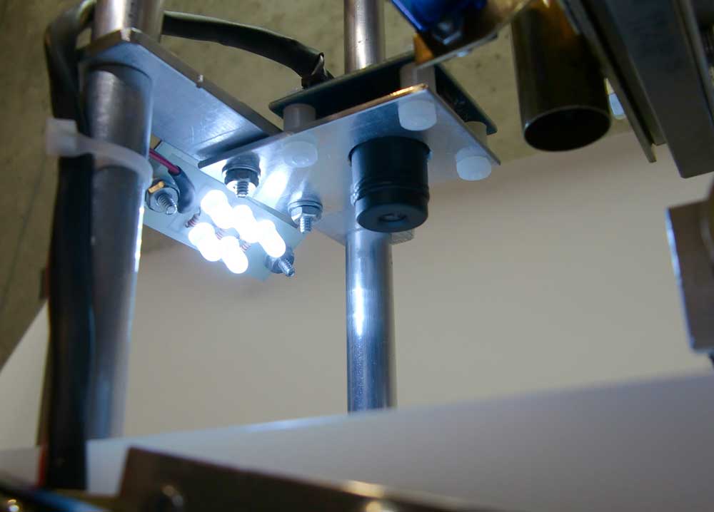
Line scan camera and illumination section. The TSL-1401 linescan camera captures 128 bits of data in a single line. Exposure time is about 1/200 sec.
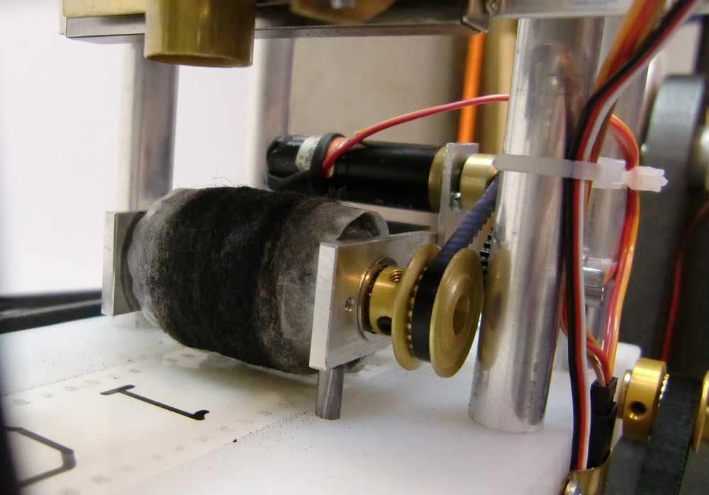
View of the erase section from the back. The mechanism is raised and lower with the small pin that comes through the base of the head. This pin rides on a cam attached to a servo.
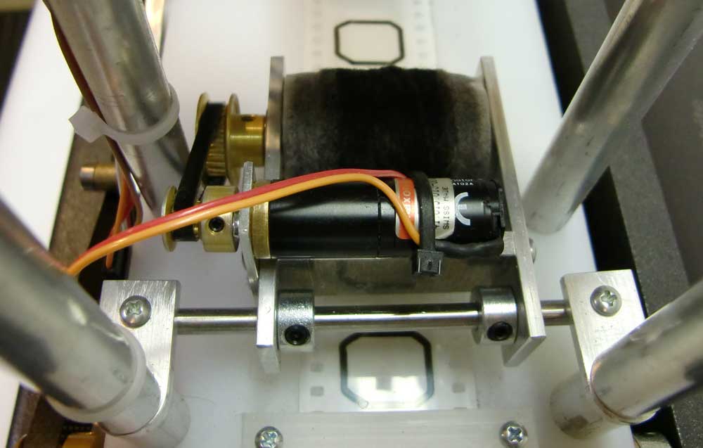
The erase section from the top. The erase cylinder is covered with 1/4" thick felt. The whole erase section pivots when it is raised and lowered on a small shaft attached to the frame.
Console and Circuit Boards
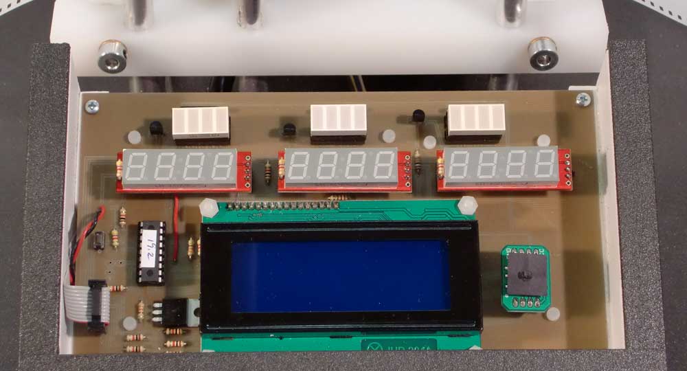
The console located in front of the read/write head contains the microcontroller and display hardware. User control of the machine consists of a 5-position switch and a 20x4 character LCD display. The console also houses a SD card slot on the left side.
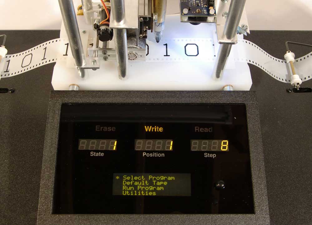
User controls and feedback console. While the Turing machine is running a program the three 4-character 7-segment LED displays provide information on state, tape position and number of steps.
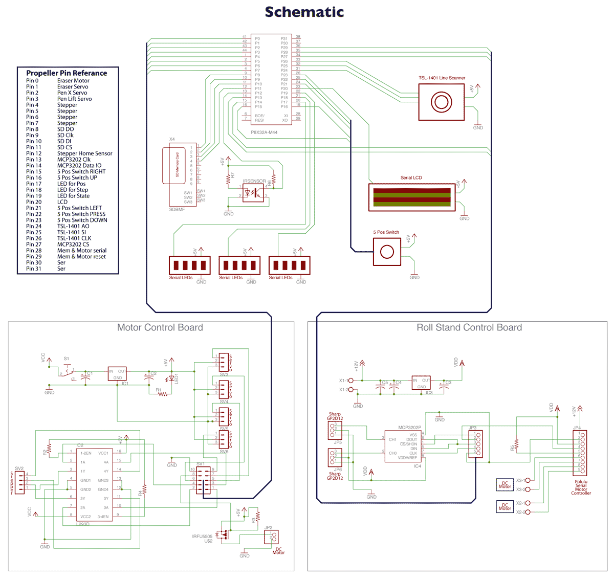
Schematic of the electrical components of the Turing machine. Schematic as PDF.
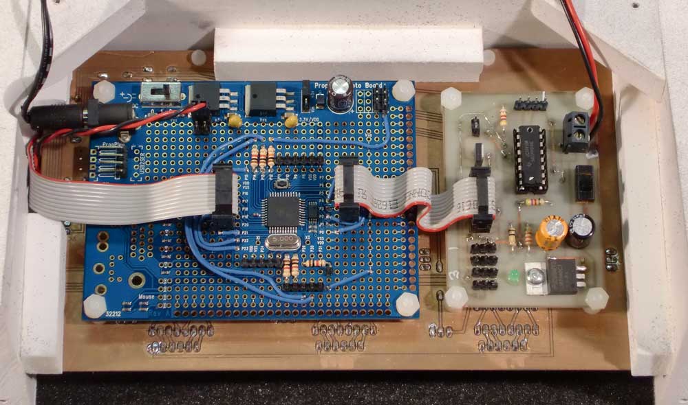
Control of all operations is handled with a Parallax Propeller chip (blue PCB on left). The machine uses all of the Propeller's 32 I/O pins. The custom board on the right supplies power and control for the stepper motor and servos.
The custom display board features a serial LCD display, three serial LED displays, three LED light bars, and a 5-position switch.
Roll Stands
The two roll stands automatically handle the excess tape at either side of the read/write head. The supply and take up rolls are mounted directly to DC gearhead motors. The small wire arm located in the gap between the roll stand and the read/write head maintains tension on the tape.
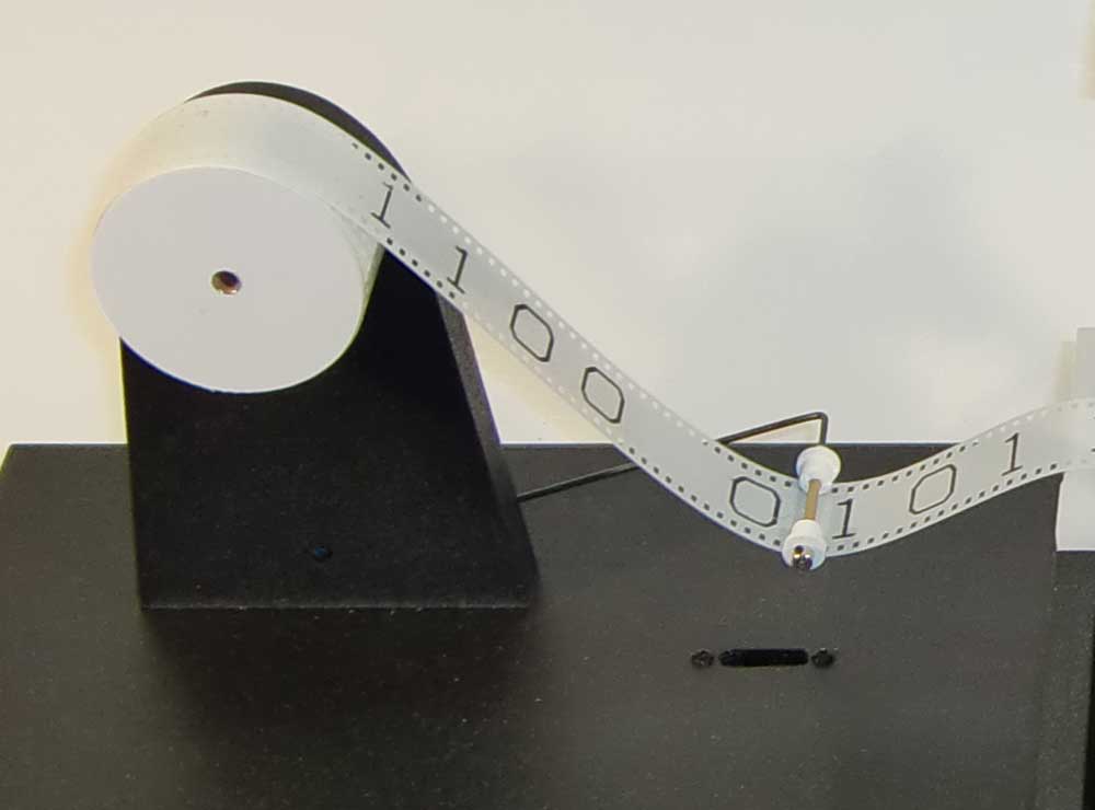
The left roll stand. Each stand is fit with a 4 RPM DC gearhead motor. The hole in the base of the machine houses an IR range sensor.

This is the IR range sensor located in the base of the machine. The motors and sensors are controlled by a program running in a separate cog of the Propeller chip.
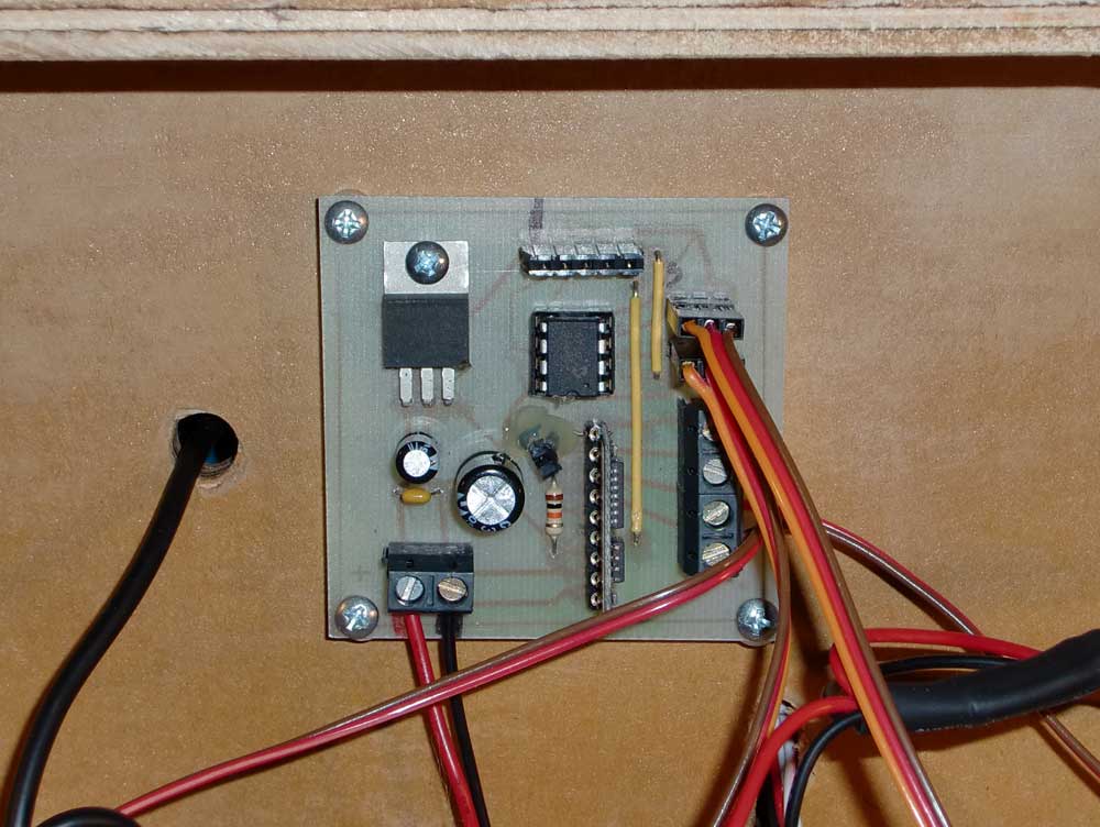
This custom PCB is in the base of the machine and provides power and connections to the roll stand sensors and motors.
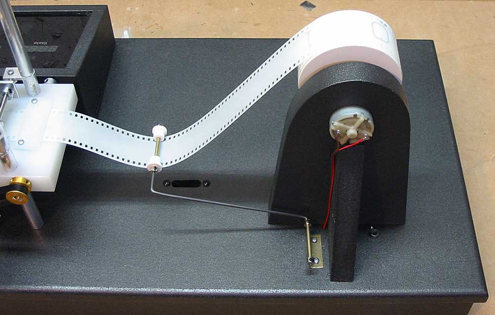
Back view of one of the roll stands. Here you can see the DC gearhead motor mounted into the stand and the wire swing arm.